
BlinkenSort with Sound - The Sound of LED Sorting Algorithms with Raspberry Pi 3 and APA102 or SK9822 LEDs
Posted on 2019-08-02 19:00 by Timo Bingmann at Permlink with 0 Comments. Tags: #sorting #electronics #LEDs #sound of sorting #frontpage #blinken-algorithms
Once BlinkenSort successfully showed fascinatingly complex sorting algorithms on an LED strip using an ESP8266 (see other article), I naturally ventured to add the sound output from the Sound of Sorting program. This turned out much harder than initially thought, because the sound generation software required more processing power than available in the cheap standard microcontrollers. After much trail and error, I found out that a sufficiently new Raspberry Pi (I happened to have a Pi 3 model B) has the rare combination of enough compute power, can drive an LED strip directly via SPI, and has an audio line-out.
The Raspberry Pi, however, cannot drive the same type of LED strip reliably as the ESP8266 can, because the Raspberry Pi runs a time-shared Linux system instead of a real-time program. But it can drive the more expensive APA102 or SK9822 LEDs which have a separate clock line. These are 4-pin LED strips with clock and data, which can easily be attached to the Pi's SPI output pins. Furthermore, the APA102 LEDs can be driven at a much higher refresh rate than the WS2812B and SK6812, due to the extra clock signal. This ultimately makes the sorting animations even smoother than with the ESP8266 (where the frame rate is already unnoticeable). I could not find any off-the-shelf library to drive the APA102 with a C++ program on the Pi, but it was trivial to write a frame buffer class and access the /dev/spi0.0 devices directly.
Then there was the question of adding a display. And after more experimentation, I found the MAX7219 dot LED matrix modules work well. These can also be driven by SPI from the Pi, which actually has two SPI outputs on the models with 40 pins. And as a bonus these dot LED matrix models can pull off an amazing frame rate. That means that besides showing the algorithm name, the super-fast refresh rate enables displaying of (nearly) every comparison counter increment, despite the human viewer only being able to see around 25 changes per second. Simply adding a HDMI display to the Pi would have also worked, but the LED matrix is cooler and has a retro feeling to it.
As you can see in the following YouTube video, each algorithm does something quite different which makes this a very interesting art installation with deep connections to informatics. BlinkenSort currently contains the following eighteen sorting algorithms (listed in the same order as in the video): MergeSort, Insertion Sort, QuickSort (LR) Hoare, QuickSort (LL) Lomoto, QuickSort Dual Pivot, ShellSort, HeapSort, CycleSort, RadixSort-MSD (High First), RadixSort-LSD (Low First), std::sort, std::stable_sort, WikiSort, TimSort, Selection Sort, Bubble Sort, Cocktail-Shaker Sort, and BozoSort. Besides sorting algorithms the collection also contains four hash table implementations: Linear Probing Hash Table, Quadratic Probing Hash Table, Cuckoo-Hashing with two places, and Cuckoo-Hashing with three places.
The video above (https://youtu.be/kAjQ8shElP8) shows the LED strip with sound in action and I added a voice-over commentary about the algorithms. There is also a second YouTube video available, without my commentary.
All source code for the sorting algorithms and other Neopixel animations is available from Github:
https://github.com/bingmann/BlinkenAlgorithms.git
Construction Manual for BlinkenSort with Sound on Raspberry Pi 3 with APA102 or SK9822 LEDs
The project is made out of the following parts:
-
APA102 or SK9822 LED strip (below: APA102, 5 meters, 96 LEDs/m, IP65, black PCB).
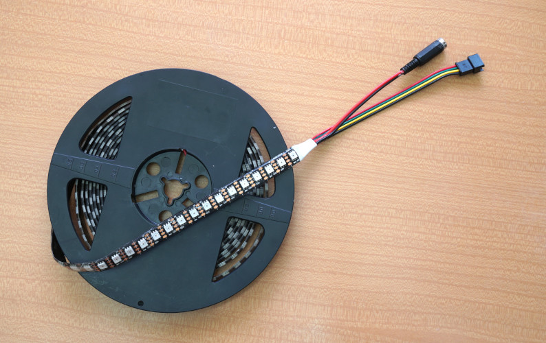
Price: ~39 Euro.
My preferred type: Aliexpress/BTF-Lightning
The strip in the picture has 96 LEDs/m, I would recommend less: 60 LEDs/m as these are cheaper. The 96 LEDs/m pitch however has smaller, nearly square "pixels".
WS8212B, SK6812 will NOT WORK properly with a Raspberry Pi. The SK9822/APA102 have 4-pins with a separate clock line.
The strips come with a 4-pin plug for attaching it to the Raspberry Pi.
-
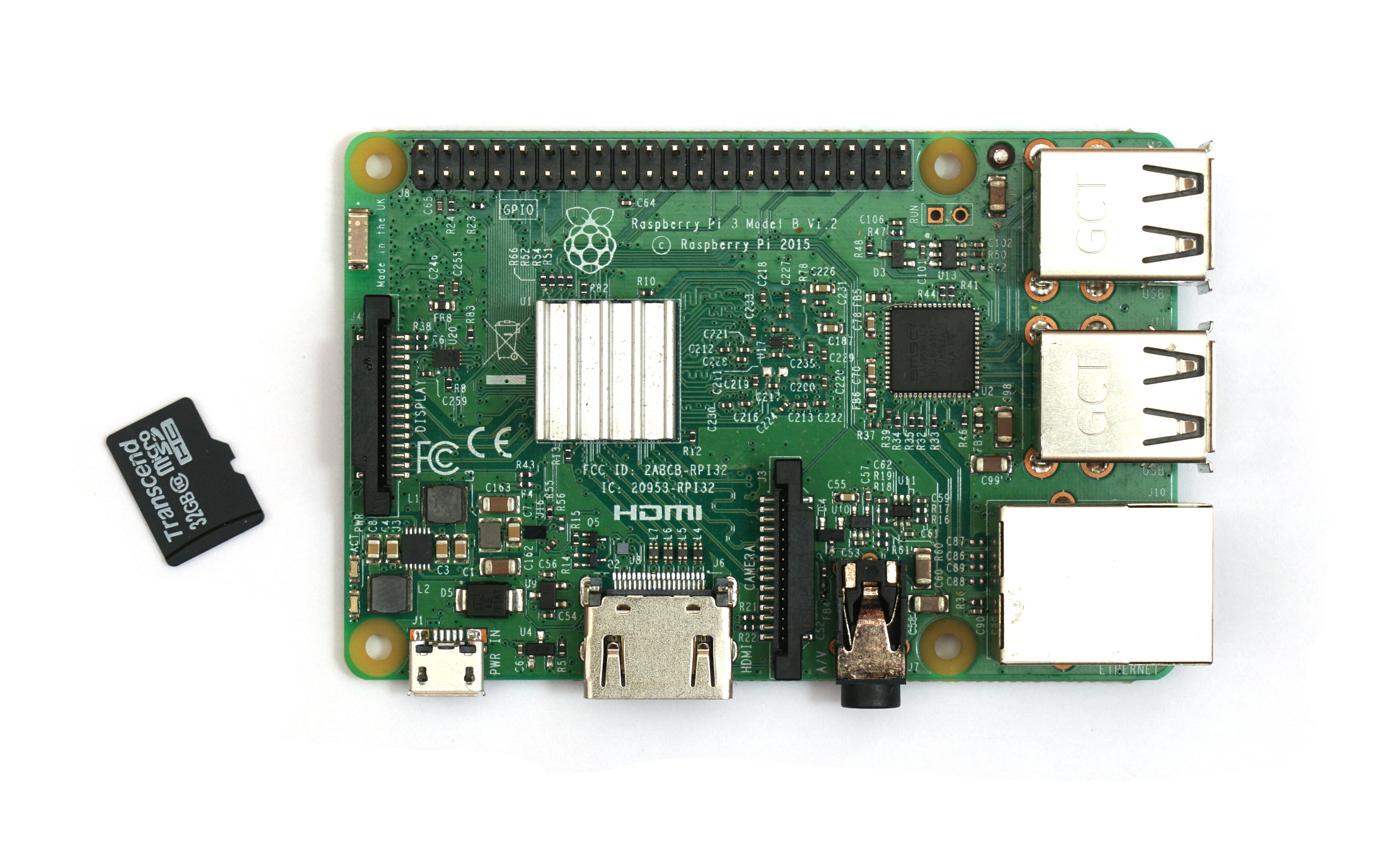
Raspberry Pi 3 Model B+ with SD Card.
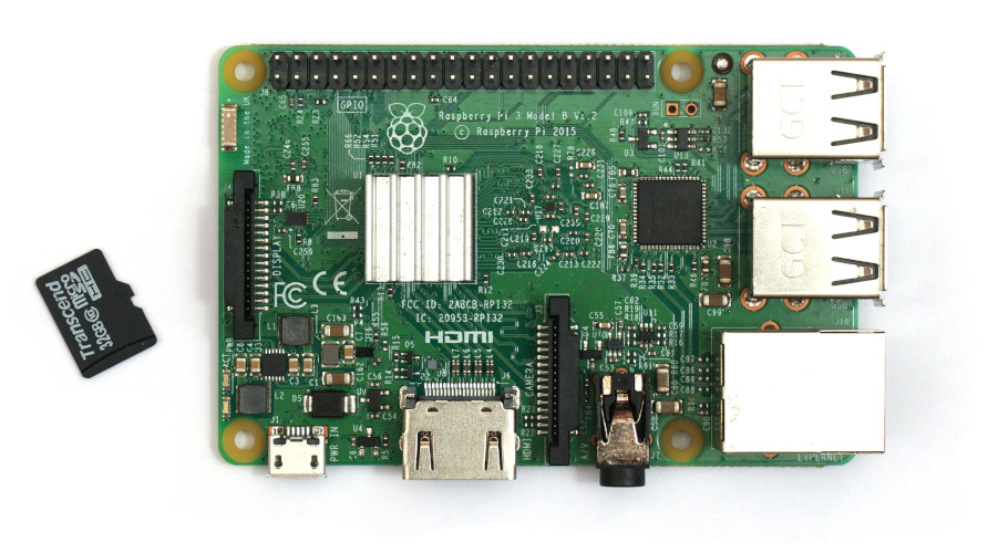
Price: ~40 Euro.
I happened to have Raspberry Pi 3 model B+ with 32 GB MicroSD card. Other models and clones, older or newer, with 40 pin header may work too. However, I think at least a quad-core ARM SoC is required for sound generation.
Raspberry Pis can be bought from the major local hardware dealers or Aliexpress/JunRoc.
My Raspberry Pi in the picture received a 14x14x10mm heat sink (Aliexpress/En-Labs, 2.50 Euro for 10 pieces) after growing hot.
-
Hookup Material: a 2x20 female socket 2.54 mm pitch pin header, (optionally) a small piece of prototyping PCB, some wires.
Price: < 5 Euro.
My preferred type: 2x20 pin header Aliexpress/A+A Technology (10 pieces), and some scrap prototyping PCB.
-
Any 5 volt 3 ampere power supply and a matching (female) power plug.

Price: ~8 Euro.
I just reused an older adjustable power supply (set to 5V). I would stay away from USB switching power supplies due to the noise induced on the Pi's sound output.
Examples: 5V/3A power supply and 2.1mm/5.5mm screw plugs.
-
Optionally: 16 × MAX7219 Dot LED Matrix Display, 8×8 pixel each.
Price: ~24 Euro.
My preferred type: 4 × Aliexpress/GreatWallElectronics
This is a pretty large display (26mm × 6.5mm), I constructed it by gluing together 2×2 boards, each board containing four pre-assembled MAX7219 modules.
For nicer hookup I also got a 5-pin ribbon cable (Aliexpress/YJBCo) and some 5-pin JST connectors like the LED strip has (Aliexpress/YJBCo).


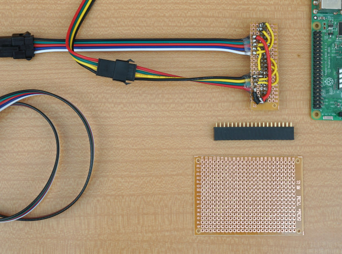
Soldering the Pin Socket "Hat" for the Raspberry Pi
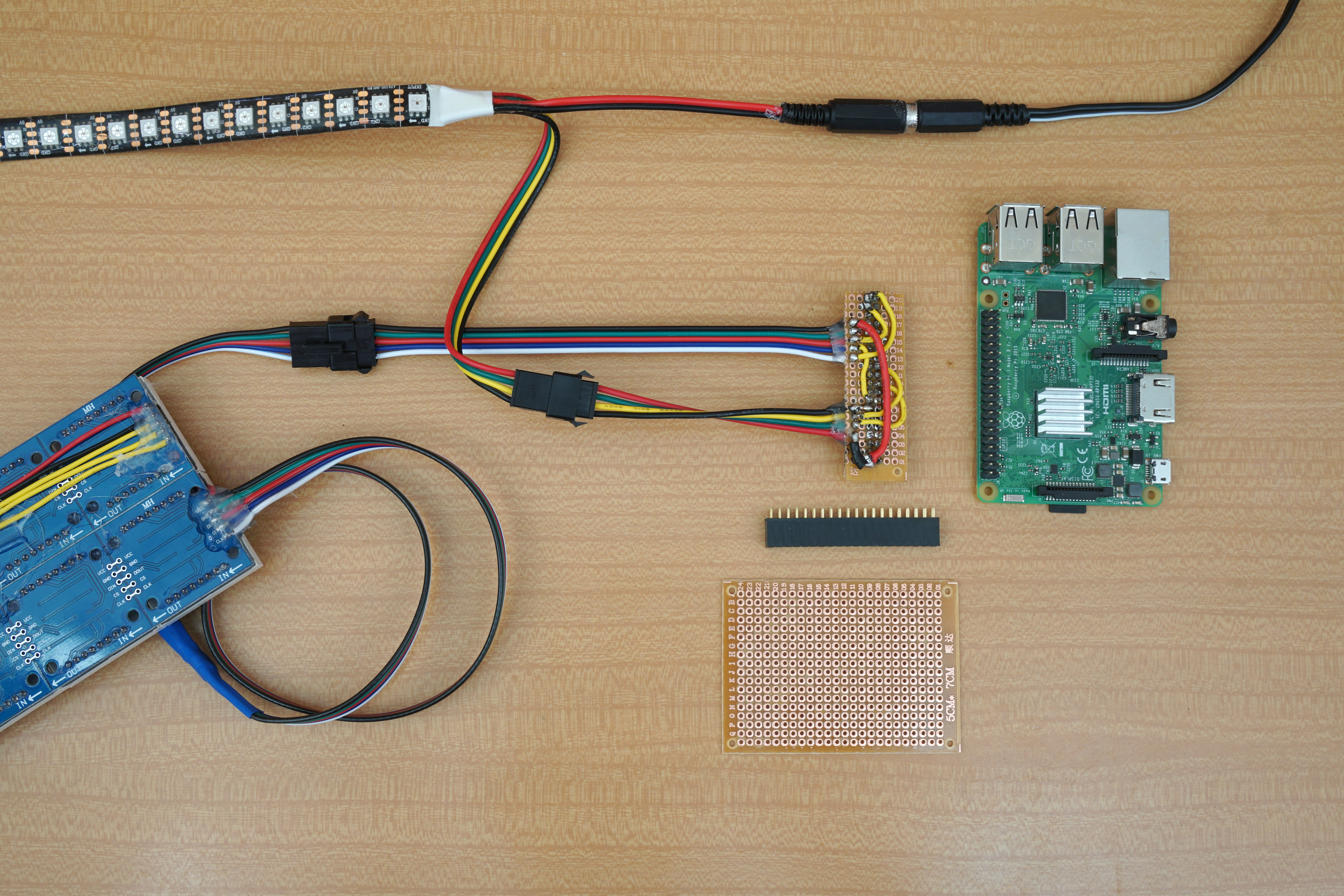
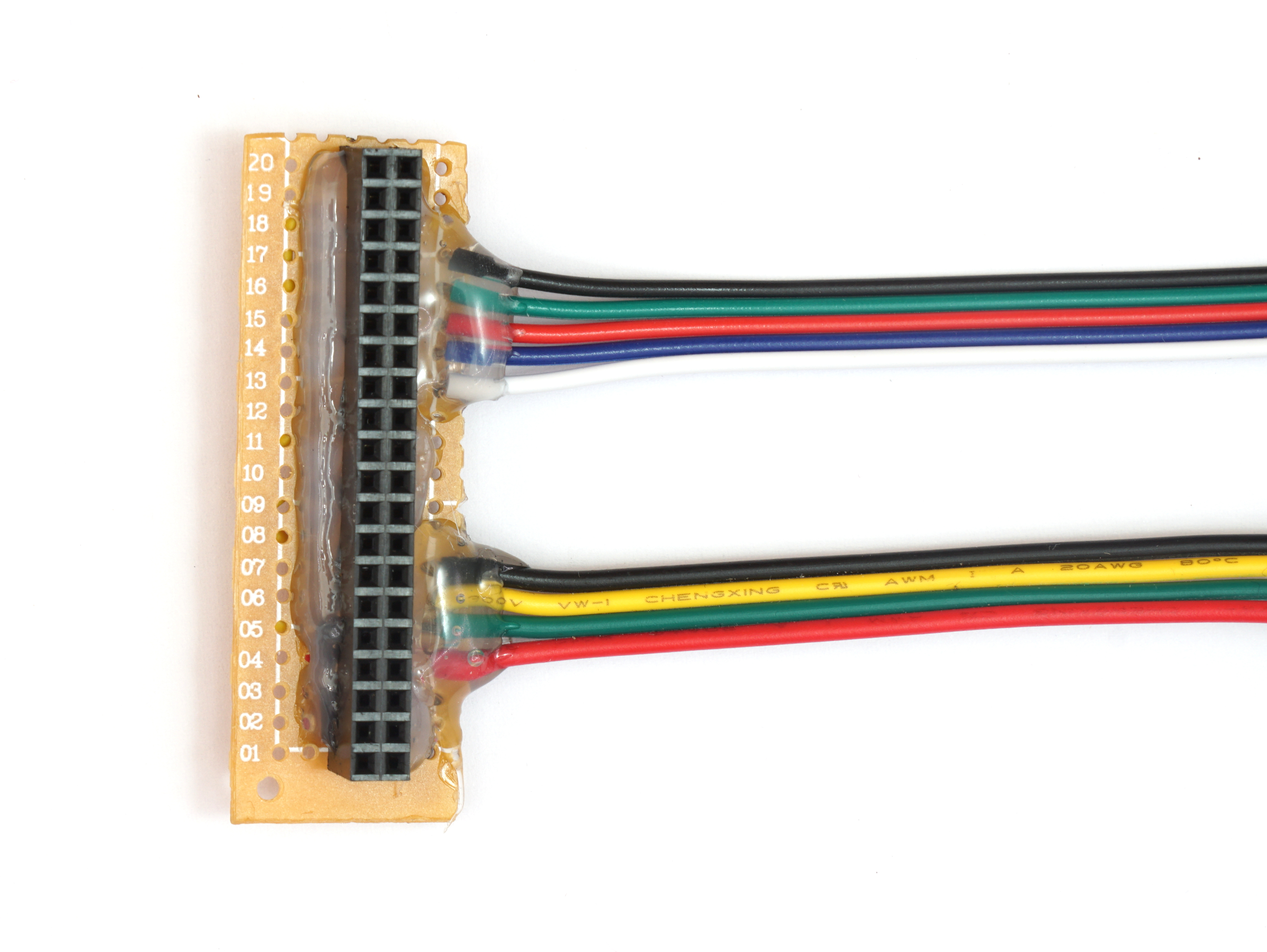
To be able to attach and remove the LED project from the Raspberry Pi quickly and conveniently, I decided to make a custom "hat" board for the 2x20 pin header on the Pi. The only parts which need to be connected are the 4-pin LED strip cable to the first SPI interface of the Pi, and optionally the 5-pin LED matrix cable to the second SPI interface. Since the required pins are somewhat stretched apart on the 2x20 pin header, I cut a small prototype PCB to route the wires to the ribbon cables.
I recommend NOT to solder all pins of the 2x20 socket (as I did in the pictures), instead only use those pins you need and maybe a few additional ones for stability.
The LED strip has 4 wires: red for 5V power, green for SPI data, yellow for SPI clock, and black for GND.
Use copious amounts of hot glue to stabilize the socket header and to fixate the cable to the PCB, such that pulling on the cable will not break any connections.
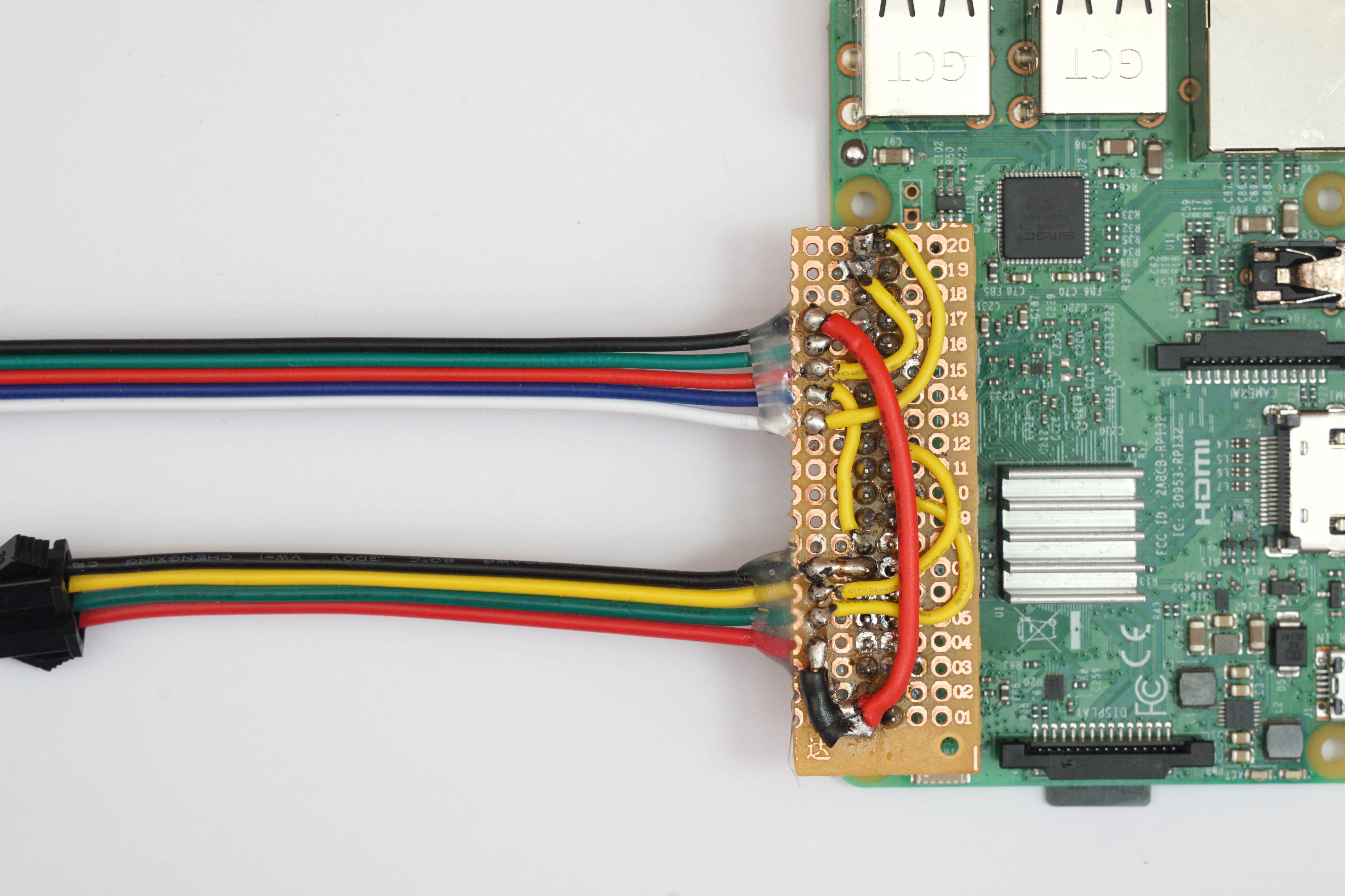
You can find the necessary pins below: red is 5V goes to 02 or 04, green is SPI data goes to pin 19, yellow is the SPI clock line and goes to pin 23, and black is ground and can be attached to any GND pin. More details on the SPI pinout of the Raspberry Pi can be found on the linked website.
As in the ESP8266 project, I find it convenient to attach the 5V power supply to the LED strip's second pair of wires as it consumes a lots of power when completely lit. The Raspberry Pi is then powered via the red/black wires in the 4-pin connector by attaching it to the correct pins in the header.
| Raspberry Pi 3 2x20 Pin Header | ||||
| Matrix display SCLK <- SPI1 SCLK | 40 | 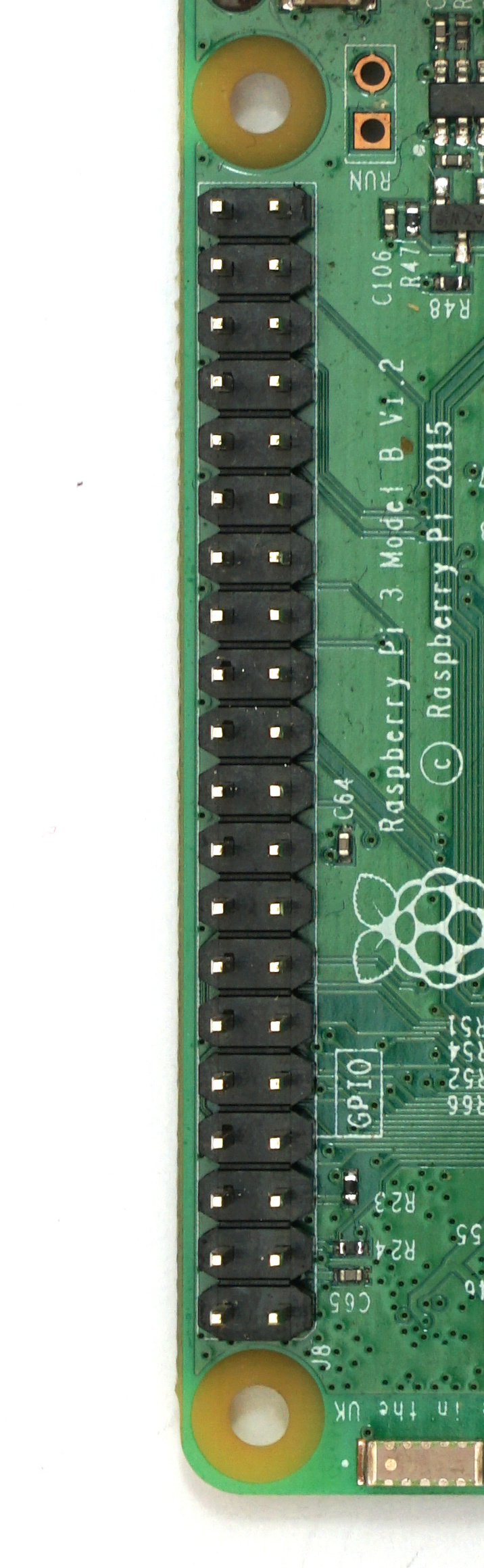 | 39 | GND |
| Matrix display SCLK <- SPI1 MOSI | 38 | 37 | ||
| 36 | 35 | |||
| Matrix display GND <- GND | 34 | 33 | ||
| 32 | 31 | |||
| GND | 30 | 29 | ||
| 28 | 27 | |||
| 26 | 25 | GND | ||
| 24 | 23 | SPI SCLK -> LED strip clock wire (yellow) | ||
| 22 | 21 | |||
| GND | 20 | 19 | SPI MOSI -> LED strip data wire (green) | |
| 18 | 17 | |||
| Matrix display CS <- GPIO 23 | 16 | 15 | ||
| LED strip ground (black) <- GND | 14 | 13 | ||
| 12 | 11 | |||
| 10 | 09 | |||
| 08 | 07 | |||
| GND | 06 | 05 | ||
| LED strip 5V power (red) + bridge to 02 <- 5V | 04 | 03 | ||
| Matrix display 5V VCC + bridge to 04 <- 5V | 02 | 01 |
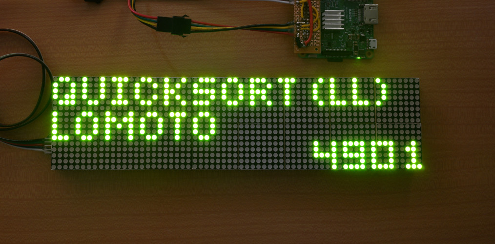
Optionally Connecting the MAX7219 Dot LED Matrix Display
Building the large MAX7219 dot LED matrix display is quite a hassle. My version of the display is held together with lots of hot glue on the inside. Alignment of the modules is critical otherwise you won't be able to read the letters. The MAX7219 form a chain of 8×8 matrix modules, which means the boards have to be connected in serial on the underside. Again lots of hot glue to keep the wires in place. Overall it turned out pretty good. It requires an amazing amount of power though (measured by how warm it gets).
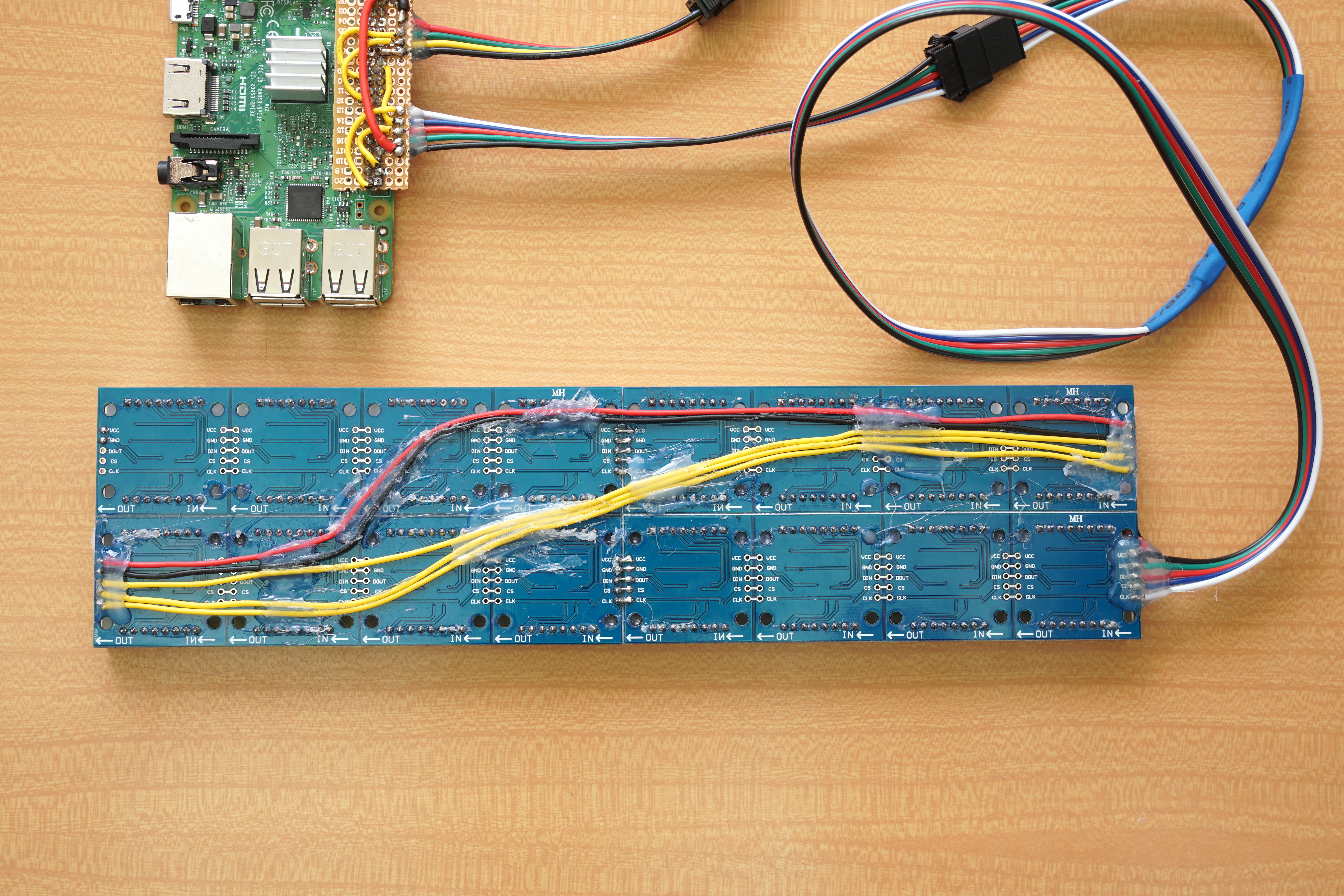
The MAX7219 dot led matrix display boards have 5 connections: VCC (5V) power, GND, DIN/DOUT (SPI data), CS (SPI chip select), and CLK (SPI SLCK clock). I directly connected the 5-pin ribbon cable to the first LED matrix module with the following unusual coloring: VCC (black), GND (green), DIN/DOUT (red), CS (blue), CLK (white). The ribbon cable is attached to a 5-pin JST connector, and the connector is glued to the "hat" board.
The MAX7219 chain is connected to the Raspberry Pi's second SPI controller. SPI data (DIN/DOUT) is attached to pin 38 (SPI1 MOSI), SPI clock (CLK) is attached to pin 40 (SPI1 SCLK), and SPI chip select (CS) is attached to pin 16. Pin 16 is not a special pin, it is GPIO pin 23 as counted by the kernel (not WiringPi). Pin 16 / GPIO23 is switched directly by the BlinkenAlgorithms program to control the LED matrix display. Due to the power consumption of the LED matrix display, I used a pretty thick red wire for the 5V connection from the LED strip's power wire. That was probably overkill.
Installing Raspbian and BlinkenAlgorithms
Download the current version of Raspbian lite from https://www.raspberrypi.org/downloads/raspbian/. Direct link: raspbian_lite_latest, which delivered 2019-07-10-raspbian-buster-lite.zip at the time of writing. Unzip the download and write the .img file to the microSD card.
I like to configure the Raspberry Pi via ssh by attaching it to a local network. Due to security, the ssh server is disabled by default, but can easily be activated by creating an empty file ssh in the "boot" partition on the SD card.
# find Raspberry Pi on the LAN using nmap and log in via ssh, default password is "raspberry"
$ nmap -sP 192.168.77.*
(list of hosts)
$ ssh [email protected]

# change the  default password
$ passwd

# reconfigure Raspberry Pi setting
$ sudo raspi-config

# change two settings:
# 2 Network Options > N1 Hostname: change to "sortpi"
# 5 Interfacing Options > P4 SPI: enable SPI
# exit raspi-config
$ sudo reboot # (or select reboot in raspi-config)

# after reboot, ssh again and update and install packages
$ sudo apt update
$ sudo apt upgrade
$ sudo apt install git build-essential screen cmake cmake-curses-gui libsdl2-dev

# turn up volume to 90% (or use alsamixer)
$ amixer -c 0 sset PCM,0 90%
$ sudo alsactl store

# enable secondary SPI interface:
$ sudo sh -c "echo 'dtoverlay=spi1-1cs' >> /boot/config.txt"
$ sudo reboot
Download the BlinkenAlgorithms repository and compile and run BlinkenSort:
# get the BlinkenAlgorithms code repo
$ git clone -b v2019.0 https://github.com/bingmann/BlinkenAlgorithms.git

# build BlinkenSort with Sound for Raspberry Pi
$ cd BlinkenAlgorithms/blinken-sort-sound-pi
$ mkdir build
$ cd build
$ cmake ..
$ make
$ ./blinken-sort
Setup to automatically run on boot up:
# write systemd service file
$ sudo nano /etc/systemd/system/blinken-sort-tty1.service

# and paste the following into the editor
[Unit]
Description=BlinkenSort tty1-service
After=getty.target
[email protected]

[Service]
Type=simple
ExecStart=/usr/bin/screen -S myTTY1 /home/pi/BlinkenAlgorithms/blinken-sort-sound-pi/build/blinken-sort
StandardInput=tty-force
StandardOutput=inherit
StandardError=inherit
User=pi

[Install]
WantedBy=multi-user.target
# end of file, ctrl+x to exit nano

# reload systemd files and enable and start the new service
$ sudo systemctl daemon-reload
$ sudo systemctl enable blinken-sort-tty1.service
$ sudo systemctl start blinken-sort-tty1.service

# check that blinken-sort is running
$ ps x

# reboot the system and check again that blinken-sort is running
$ sudo reboot
$ ps x
Optionally: Printouts of Some of the Algorithms
For one of the installations, I made full-page printouts of some the algorithm's code:
SoLS-Algorithms-Printout.pdf ![]() , LaTeX source file SoLS-Algorithms-Printout.tex.
, LaTeX source file SoLS-Algorithms-Printout.tex.
Optionally: Set Up Both WiFi Station and an Access Point (AP)
While it is easy to connect the Raspberry Pi to a local WiFi access point, such that one can log in and change the BlinkenAlgorithms code, I take the LED strips to many places to show people. There it is much harder to log in to the Pi due to the missing local WiFi config on it. Hence, the Pi opening an access point itself is a better solution. That is possible using hostapd and dnsmasq. However, configuring both station and access points modes with the same internal WiFi chip is surprisingly difficult.
I collected a tutorial to set up both WiFi station and an access point which worked on 2019-07-10-raspbian-buster-lite.zip. Your mileage may vary in future versions.
